In the previous section we completed a discussion on light rays. In this section, we will learn about Current electricity.
1. Consider the positively charged electroscope in fig 8.1 below.
• The above fig. is obtained from wikipedia.
2. This electroscope can be connected to the earth by a conductor through a switch.
• When the switch is turned on, charge will flow through the conductor.
3. Why do we say that there is 'flow of charge'?
• When the switch is 'turned on', electrons flow from the earth towards the electroscope.
• These electrons will neutralise the positive charge.
• So we say that there is a 'flow of charge'
■ But this 'flow of charge' will stop within a short time.
An activity:
1. Consider the circuit shown in fig.8.2 below:
• It consists of a cell, a bulb and a switch
2. When the switch is turned on, the bulb will glow.
■ The bulb will glow continuously.
• This indicates that unlike in the electroscope, the 'flow of charge' in this case is continuous.
• A 'flow of charge' creates a current.
■ In conductors, current is formed by the flow of electrons
• But in gases and electrolytes, electrons cannot flow freely
■ So in gases and electrolytes, the current is formed by the flow of ions
• For many practical applications, we want a continuous flow of charge as we saw in fig.8.2
• An instantaneous flow as in the case of the electroscope in fig.8.1 is not sufficient
Let us see a comparison between 'flow of charge' and 'flow of water'. We will write the comparison in steps:
1. Consider fig.8.3(a) below:
• In the arrangement in fig.a, water at P is at a higher level than Q.
2. When we open the valve, water will flow from P to Q
• As a result of this flow, the wheel will spin
3. But after some time, the levels at P and Q become the same.
• Then water will no longer flow from P to Q.
• So the wheel will no longer spin. This is shown in fig.b
• So we can write: The flow of water was due to the 'difference in water levels' between P and Q
4. We can write it in a more scientific way:
(i) Water at both P and Q have potential energy. We have seen potential energy here.
(ii) But water at P is at a higher level. So it has more potential energy than at Q
(iii) In other words. there is a 'difference in potential energy' between P and Q.
(iv) It is this 'difference in potential energy' that causes the water to flow.
(v) In fig.b, both P and Q are at the same level. So there is no difference in potential energy between P and Q. So the water will not flow.
5. In the case of electric circuits also, a similar case as in fig.8.3(b) occurs. Consider fig.8.4 below:
• A bulb is connected to a conductor through a switch.
6. There is no 'difference in potential' between X and Y.
• So when the switch is turned on, there will not be any flow of charge and so, the bulb will not glow.
7. The flow of water in fig.8.3(a) soon comes to an end.
■ Can we achieve a continuous flow? Let us try:
• In fig.8.5 below, a pump is introduced. All other arrangements are the same as in fig.8.3
8. Now, what does this pump do?
(i) The pump has an inlet pipe and an outlet pipe
♦ The inlet pipe takes in water from Q
♦ The outlet pipe delivers the water to P
(ii) The blue portion attached to the pump is like a closed vessel.
• Inside this vessel, there are rotating blades.
• Rotation of the blades is achieved with the help of the motor.
(iii) Due to the rotation of those blades, water will be sucked from Q.
(iv) Due to the continuing rotation of the blades, this sucked up water will be sent upwards into the outlet pipe of the pump. Thus the water will reach P
9. The pump has it's own definite 'rate of flow'.
• That is., in one second, it will deliver a 'fixed litres' of water. We cannot change it
• But we can adjust the valve at the bottom. By adjusting this valve, we can ensure that the following two values are the same:
(a) The litres of water reaching P from Q (through the pump) in one second
(b) The litres of water reaching Q from P (through the value) in one second
If the above two items are equal, we will achieve the following conditions:
(i) Level of water at P does not change
(ii) Level of water at Q does not change
10. In other words, the 'difference in water levels' between P and Q does not change
• If this 'difference in water levels' is maintained in this way, there will be continuous flow of water from P to Q, and thus the wheel at the bottom will spin continuously.
11. In the same way, we want the bulb in fig.8.4 to glow continuously
• The wheel in fig.8.5 spins continuously because there is a 'difference in energy level is maintained continuously'
♦ The quantity of energy at P is EP
♦ The quantity of energy at Q is EQ
12. Since EP ≠ EQ, there is a 'difference in energy level' between P and Q
■ What type of energy is EP and EQ?
• Is it Potential energy?
• Is it Kinetic energy?
• Is it Chemical energy?
• Is it Solar energy?
- - -
- - -
• Obviously, it is potential energy.
13. In the same way,
• We want some energy EX at X in the fig.8.4
• We want some energy EY at Y in the fig.8.4
• Also we want EX ≠ EY
14. But what type of energy is EX and EY?
• Is it Potential energy?
• Is it Kinetic energy?
• Is it Chemical energy?
• Is it Solar energy?
- - -
- - -
■ In this case, the energy is called electric potential
• EX is a particular value of 'electric potential' at X
• EY is a particular value of 'electric potential' at Y
■ This is similar to saying:
• EP is a particular value of 'potential energy' at P
• EQ is a particular value of 'potential energy' at Q
15. But in problems, we will be more interested in the difference: (EP - EQ)
• For example, using (EP - EQ), scientists and engineers can calculate the speed at which the wheel will spin
16. In the same way, for our present problem in fig.8.4, we are more interested in (EX - EY)
• For example, using (EX - EY), scientists and engineers can calculate the brightness with which the bulb will glow
• So the 'difference between two potential energies' will also be measured in joules
■ The unit of 'electric potential' is volt
■ So the 'difference between two electric potentials' will also be measured in volts
For example:
• If EP = 14 joules and EQ = 5 joules, then (EP - EQ) = 9 joules
• If EX = 8 volts and EY = 3 volts, then (EX - EY) = 5 volts
[Note that 'unit' is just a way for measuring. There can be several ways for measuring a quantity
For example: A certain length can be measured in cm or inch. They will give different values. But the actual length does not change.]
• For measuring 'electric potential', the unit 'volt' is universally accepted
■ If the potential difference between X and Y is 5 volts, we say this:
'A voltage of 5 volts is available between X and Y'
18. So our next task is to apply a potential difference between X and Y in fig.8.4.
• Also to make the bulb glow continuously, we have to maintain that potential difference
19. In the case of the spinning wheel, we used a pump, which is an 'external source of energy' to maintain the difference in water levels
• For our circuit in fig.8.4 also, we will need an 'external source of energy'.
• This 'external source of energy' that we will use is called a cell.
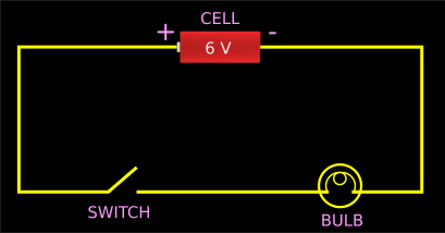
20. In fig.8.6 below, a cell is connected to the circuit. It is a 6 V cell.
• That means, it is able to maintain a potential difference of 6 volts.
• Note that X is connected to the positive terminal of the cell. So X will get a potential of 6 volts.
• Y is connected to the negative terminal of the cell. So Y will get a potential of zero volts.
• Thus the potential difference between X and Y is (6-0) = 6 volts.
21. The cell is an external source of energy. It continuously supplies 6 volts of energy.
• So the 'potential difference' between X and Y is maintained as 6 volts.
• Thus, when the switch is turned on, the bulb will glow continuously.
How is the cell able to supply this potential difference?
• Inside the cell there are chemical substances.
• When we connect a cell to a circuit, and the switch is turned on, chemical reactions will begin between these substances.
• As a result, there will be a flow of electrons.
■ But is the cell able to maintain the 'flow of electrons' for very long periods?
• The answer is 'no'. We know that, when chemical reactions takes place, the reactants will be converted into products.
• So when all the reactants stored in the cell are converted into products, the reactions will no longer take place.
• So there will not be any further flow of electrons. We will learn more details in higher classes.
• At present, all we need to know is that, a cell is an 'external source of energy'.
• It can help to maintain a 'potential difference'.
• But how much potential difference do we need?
♦ If it is a large bulb, we will need a large potential difference
♦ If it is a small bulb, we will need only a small potential difference
2. So before buying a cell we must decide how much energy we will need to make the bulb glow.
• This 'required energy' is specified in terms of electromotive force.
■ Electromotive force is defined as the energy provided by a cell which gives us the ability to maintain the potential difference between the ends of a conductor. It is measured in volts.
• In short form, the electromotive force is written as emf
3. If a cell is marked as 1.5 V, then it's emf is 1.5 volts.
• That is., if we use that cell, we will be able to maintain a potential difference of 1.5 volts between the ends of a conductor. This is shown in fig.8.7 below:
4. But when the electrons flow through the conductor some energy will be lost as heat.
• So if we want to check the emf of a cell using a 'measuring device', we must connect the terminals of the 'measuring device' directly to the terminals of the cell.
5. The voltmeter is such a 'measuring device'.
• The positive terminal of the cell should be connected to the positive terminal of the voltmeter.
• The negative terminal of the cell should be connected to the negative terminal of the voltmeter
• This is shown in fig.8.8 below:
1. Consider the positively charged electroscope in fig 8.1 below.
 |
| Fig.8.1 |
2. This electroscope can be connected to the earth by a conductor through a switch.
• When the switch is turned on, charge will flow through the conductor.
3. Why do we say that there is 'flow of charge'?
• When the switch is 'turned on', electrons flow from the earth towards the electroscope.
• These electrons will neutralise the positive charge.
• So we say that there is a 'flow of charge'
■ But this 'flow of charge' will stop within a short time.
An activity:
1. Consider the circuit shown in fig.8.2 below:
 |
| Fig.8.2 |
2. When the switch is turned on, the bulb will glow.
■ The bulb will glow continuously.
• This indicates that unlike in the electroscope, the 'flow of charge' in this case is continuous.
• A 'flow of charge' creates a current.
■ In conductors, current is formed by the flow of electrons
• But in gases and electrolytes, electrons cannot flow freely
■ So in gases and electrolytes, the current is formed by the flow of ions
• For many practical applications, we want a continuous flow of charge as we saw in fig.8.2
• An instantaneous flow as in the case of the electroscope in fig.8.1 is not sufficient
Let us see a comparison between 'flow of charge' and 'flow of water'. We will write the comparison in steps:
1. Consider fig.8.3(a) below:
 |
| Fig.8.3 |
2. When we open the valve, water will flow from P to Q
• As a result of this flow, the wheel will spin
3. But after some time, the levels at P and Q become the same.
• Then water will no longer flow from P to Q.
• So the wheel will no longer spin. This is shown in fig.b
• So we can write: The flow of water was due to the 'difference in water levels' between P and Q
4. We can write it in a more scientific way:
(i) Water at both P and Q have potential energy. We have seen potential energy here.
(ii) But water at P is at a higher level. So it has more potential energy than at Q
(iii) In other words. there is a 'difference in potential energy' between P and Q.
(iv) It is this 'difference in potential energy' that causes the water to flow.
(v) In fig.b, both P and Q are at the same level. So there is no difference in potential energy between P and Q. So the water will not flow.
5. In the case of electric circuits also, a similar case as in fig.8.3(b) occurs. Consider fig.8.4 below:
 |
| Fig.8.4 |
6. There is no 'difference in potential' between X and Y.
• So when the switch is turned on, there will not be any flow of charge and so, the bulb will not glow.
7. The flow of water in fig.8.3(a) soon comes to an end.
■ Can we achieve a continuous flow? Let us try:
• In fig.8.5 below, a pump is introduced. All other arrangements are the same as in fig.8.3
 |
| Fig.8.5 |
(i) The pump has an inlet pipe and an outlet pipe
♦ The inlet pipe takes in water from Q
♦ The outlet pipe delivers the water to P
(ii) The blue portion attached to the pump is like a closed vessel.
• Inside this vessel, there are rotating blades.
• Rotation of the blades is achieved with the help of the motor.
(iii) Due to the rotation of those blades, water will be sucked from Q.
(iv) Due to the continuing rotation of the blades, this sucked up water will be sent upwards into the outlet pipe of the pump. Thus the water will reach P
9. The pump has it's own definite 'rate of flow'.
• That is., in one second, it will deliver a 'fixed litres' of water. We cannot change it
• But we can adjust the valve at the bottom. By adjusting this valve, we can ensure that the following two values are the same:
(a) The litres of water reaching P from Q (through the pump) in one second
(b) The litres of water reaching Q from P (through the value) in one second
If the above two items are equal, we will achieve the following conditions:
(i) Level of water at P does not change
(ii) Level of water at Q does not change
10. In other words, the 'difference in water levels' between P and Q does not change
• If this 'difference in water levels' is maintained in this way, there will be continuous flow of water from P to Q, and thus the wheel at the bottom will spin continuously.
11. In the same way, we want the bulb in fig.8.4 to glow continuously
• The wheel in fig.8.5 spins continuously because there is a 'difference in energy level is maintained continuously'
♦ The quantity of energy at P is EP
♦ The quantity of energy at Q is EQ
12. Since EP ≠ EQ, there is a 'difference in energy level' between P and Q
■ What type of energy is EP and EQ?
• Is it Potential energy?
• Is it Kinetic energy?
• Is it Chemical energy?
• Is it Solar energy?
- - -
- - -
• Obviously, it is potential energy.
13. In the same way,
• We want some energy EX at X in the fig.8.4
• We want some energy EY at Y in the fig.8.4
• Also we want EX ≠ EY
14. But what type of energy is EX and EY?
• Is it Potential energy?
• Is it Kinetic energy?
• Is it Chemical energy?
• Is it Solar energy?
- - -
- - -
■ In this case, the energy is called electric potential
• EX is a particular value of 'electric potential' at X
• EY is a particular value of 'electric potential' at Y
■ This is similar to saying:
• EP is a particular value of 'potential energy' at P
• EQ is a particular value of 'potential energy' at Q
15. But in problems, we will be more interested in the difference: (EP - EQ)
• For example, using (EP - EQ), scientists and engineers can calculate the speed at which the wheel will spin
16. In the same way, for our present problem in fig.8.4, we are more interested in (EX - EY)
• For example, using (EX - EY), scientists and engineers can calculate the brightness with which the bulb will glow
■ This difference in electric potential is called potential difference between X and Y
17. We know that the unit of potential energy is joules• So the 'difference between two potential energies' will also be measured in joules
■ The unit of 'electric potential' is volt
■ So the 'difference between two electric potentials' will also be measured in volts
For example:
• If EP = 14 joules and EQ = 5 joules, then (EP - EQ) = 9 joules
• If EX = 8 volts and EY = 3 volts, then (EX - EY) = 5 volts
[Note that 'unit' is just a way for measuring. There can be several ways for measuring a quantity
For example: A certain length can be measured in cm or inch. They will give different values. But the actual length does not change.]
• For measuring 'electric potential', the unit 'volt' is universally accepted
■ If the potential difference between X and Y is 5 volts, we say this:
'A voltage of 5 volts is available between X and Y'
18. So our next task is to apply a potential difference between X and Y in fig.8.4.
• Also to make the bulb glow continuously, we have to maintain that potential difference
19. In the case of the spinning wheel, we used a pump, which is an 'external source of energy' to maintain the difference in water levels
• For our circuit in fig.8.4 also, we will need an 'external source of energy'.
• This 'external source of energy' that we will use is called a cell.
20. In fig.8.6 below, a cell is connected to the circuit. It is a 6 V cell.
• That means, it is able to maintain a potential difference of 6 volts.
 |
| Fig.8.6 |
• Y is connected to the negative terminal of the cell. So Y will get a potential of zero volts.
• Thus the potential difference between X and Y is (6-0) = 6 volts.
21. The cell is an external source of energy. It continuously supplies 6 volts of energy.
• So the 'potential difference' between X and Y is maintained as 6 volts.
• Thus, when the switch is turned on, the bulb will glow continuously.
How is the cell able to supply this potential difference?
• Inside the cell there are chemical substances.
• When we connect a cell to a circuit, and the switch is turned on, chemical reactions will begin between these substances.
• As a result, there will be a flow of electrons.
■ But is the cell able to maintain the 'flow of electrons' for very long periods?
• The answer is 'no'. We know that, when chemical reactions takes place, the reactants will be converted into products.
• So when all the reactants stored in the cell are converted into products, the reactions will no longer take place.
• So there will not be any further flow of electrons. We will learn more details in higher classes.
• At present, all we need to know is that, a cell is an 'external source of energy'.
• It can help to maintain a 'potential difference'.
Electromotive force
1. In the fig.8.4 that we saw previously above, we wanted a potential difference between X and Y.• But how much potential difference do we need?
♦ If it is a large bulb, we will need a large potential difference
♦ If it is a small bulb, we will need only a small potential difference
2. So before buying a cell we must decide how much energy we will need to make the bulb glow.
• This 'required energy' is specified in terms of electromotive force.
■ Electromotive force is defined as the energy provided by a cell which gives us the ability to maintain the potential difference between the ends of a conductor. It is measured in volts.
• In short form, the electromotive force is written as emf
3. If a cell is marked as 1.5 V, then it's emf is 1.5 volts.
• That is., if we use that cell, we will be able to maintain a potential difference of 1.5 volts between the ends of a conductor. This is shown in fig.8.7 below:
 |
| Fig.8.7 |
• So if we want to check the emf of a cell using a 'measuring device', we must connect the terminals of the 'measuring device' directly to the terminals of the cell.
5. The voltmeter is such a 'measuring device'.
• The positive terminal of the cell should be connected to the positive terminal of the voltmeter.
• The negative terminal of the cell should be connected to the negative terminal of the voltmeter
• This is shown in fig.8.8 below:
 |
| Fig.8.8 |
No comments:
Post a Comment