In the previous section we saw how to connect voltmeter and ammeter to circuits. In this section, we will see the relation between voltage and current.
Let us do an activity. The steps are written below:
1. Make a circuit with the following components:
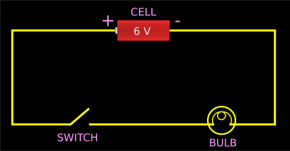
An ammeter, switch, a cell and a bulb.
• The circuit diagram is shown in fig.8.16 below:
2. Turn on the switch
• Note down the ammeter reading
• Note down the intensity of light from the bulb
• Turn off the switch. This completes one trial.
3. Add one more cell in the circuit. The two cells should be connected in series
4. Turn on the switch
• Note down the ammeter reading
• Note down the intensity of light from the bulb
• Turn off the switch. This completes the second trial.
5. Add one more cell in the circuit. The three cells should be connected in series
6. Turn on the switch
• Note down the ammeter reading
• Note down the intensity of light from the bulb
• Turn off the switch. This completes the third and final trial.
The trials are complete. The observations are tabulated below:
From the table we can make the following two conclusions:
1. When the number of cells (connected in series) increase, ammeter reading increases
• The increase in ammeter reading indicates increase in current
■ So we can write:
When the number of cells (connected in series) increase, the current in the circuit increases
2. When the number of cells (connected in series) increase, intensity of light increases
• That means, when current increases, intensity of light also increases
■ What is the reason?
We will write the answer in steps:
(i) We know that, light is produced as a result of the heating of the filament of the bulb
(ii) More current passing through the filament means that more electrons passing through it per second
(iii) So the filament will glow with more intensity
• We can write this in another way also:
When current increase, the heat produced also increases
Another activity:
This activity is performed to find the relation between current and potential difference. We will write the steps:
1. Make a circuit with the following components:
An ammeter, a voltmeter, switch, a 1.5 V cell and a 30 cm long nichrome wire.
• The circuit diagram is shown in fig.8.17 below:
2. Turn on the switch
• Note down the voltmeter reading. This reading should be entered in the table in the 'V' column
• Note down the ammeter reading. This reading should be entered in the table in the 'I' column
• Turn off the switch. This completes one trial.
3. Add one more 1.5 V cell in the circuit. The two cells should be connected in series
4. Turn on the switch
• Note down the voltmeter reading. This reading should be entered in the table in the 'V' column
• Note down the ammeter reading. This reading should be entered in the table in the 'I' column
• Turn off the switch. This completes the second trial.
5. Add one more 1.5 V cell in the circuit. The three cells should be connected in series
6. Turn on the switch
• Note down the voltmeter reading. This reading should be entered in the table in the 'V' column
• Note down the ammeter reading. This reading should be entered in the table in the 'I' column
• Turn off the switch. This completes the third and final trial.
The trials are complete. The observations are tabulated below:
• Note that, the last column is filled up by calculating V⁄I for each trial
• From the table we can make the following conclusions:
Conclusion 1: When cells are connected in series, the 'available potential difference' increases.
■ Since the potential difference is measured in volts, we say:
When cells are connected in series, voltage increases.
• When a single 1.5 V cell is connected in series, the voltmeter reading = 1.5 V
• When two 1.5 V cells are connected in series, the voltmeter reading = (1.5 × 2) = 3 V
• When three 1.5 V cells are connected in series, the voltmeter reading = (1.5 × 3) = 4.5 V
Conclusion 2:
We will arrive at this conclusion by writing the required steps:
(i) From the third and fourth columns we get:
• When voltage increases, current also increases.
(ii) This can be written mathematically as: V ∝ I
• That is., V is proportional to I
(iii) We can avoid the '∝' symbol by introducing a 'constant of proportionality'. See details here.
That is., V = (a constant) × I
⟹ V⁄I = a constant
(iv) That means:
• We can do any number of trials we like.
• In each of those trials, we can calculate V⁄I using the V and I obtained in that trial.
• Then we can compare those V⁄I values. All those values will be the same.
• This is indeed true as can be seen from the last column. All values are '10'
■ So the conclusion is:
V⁄I is a constant
• This property was first discovered by the German scientist George Simon Ohm
■ He formulated the Ohm's law. It states that:
When temperature remains constant, the current through a conductor is directly proportional to the potential difference between it's ends.
• Note that, the temperature should remain constant.
• This is important because, if we increase or decrease the temperature, the internal molecular and ionic properties of a conductor will change. So the resistance given (against the flow of current) by the conductor will change. We cannot do the calculations if the temperature changes.
• So we have: V⁄I = a constant
• This constant is given a special name: 'Resistance of the conductor' or simply 'Resistance'
• It is denoted by the letter 'R'
• So we can write: V⁄I = R
How can we apply this law to a practical situation?
We will write the answer in steps:
1. Consider the activity that we saw just above.
• We have: Current = 0.15 A (when 1.5 V cell is connected)
2. What if we want a higher current with the same 1.5 V?
• We have: V⁄I = R = 10
• That is: R = 1.5⁄I = 10
3. The current 'I' is in the denominator. So if we decrease 10, I will increase.
4. How can we decrease 10?
• We can decrease it by decreasing the length of the nichrome wire.
• That is., if we decrease the length of the nichrome wire, the 'resistance to the flow of current' will decrease.
• So the current will increase even without any increase in the number of cells.
■ The reverse is also applicable. That is., if we want to reduce the current without decreasing the voltage, we can increase the length of the nichrome wire.
■ So 'resistance' is a very convenient way to increase or decrease current. The convenience is that:
Using resistance, we can change the current without changing the voltage
• Nichrome wire is often used to provide resistance in circuits.
♦ A longer nichrome wire will give a higher resistance
♦ A shorter nichrome wire will give a lower resistance.
• Some images of nichrome wire can be seen here.
• The components in a circuit whose function is to 'provide a resistance to the flow of current' are called resistors
■ The official definition is:
Resistors are conductors used to include a particular resistance in a circuit
• Some resistors available in the market can be seen here.
• In circuit diagrams, they are shown using the symbol:

• It means that, we must know 'how much resistance' is to be provided in a circuit.
• Then only we can purchase a resistor
2. So we must be able to 'measure resistance'.
• For 'measuring resistance', we must need an appropriate unit.
3. Let us try to establish a unit:
• We know that R = V⁄I.
♦ Unit of voltage 'V' is volt
♦ Unit of current 'I' is ampere
• So unit of R is volt⁄ampere
• This 'volt⁄ampere' is given a special name: Ohm
• It's symbol is 'Ω'. It is the Greek letter 'omega'
■ So what can we say about '1 Ω'?
• That is., we want to know the peculiarity about a resistor, whose resistance is '1 Ω'
We will write the steps:
1. Consider the circuit shown in fig.8.18 below:
• A voltmeter is connected to know the 'potential difference across the two ends of a resistor'
• Recall that 'potential difference across the two ends of a resistor' is same as 'voltage across the two ends of a resistor'
• An ammeter is connected to know the current flowing through the circuit
• Let the voltmeter reading be 1 V
♦ Then we can say: The voltage between the ends of the resistor is 1 volt.
• Let the ammeter reading be 1 A
♦ Then we can say: A current of 1 ampere is flowing through the circuit.
♦ That is., a current of 1 ampere is flowing through the resistor
• So the resistance 'R' of the resistor shown in that circuit is: 1 V⁄1 A. = 1 Ω
■ The official definition is:
If a conductor connected to a voltage of one volt, passes a current 1 A, then the conductor will have '1 Ω' resistance
Using basic algebra, the equation R = V⁄I can be written in two other forms also:
• I = V⁄R
• V = IR
• We can use any one of the three equations. The choice depends on the requirements in the problem
• We can use the following triangle to remember the equations:
■ This is called the VIR triangle
• If we want to calculate V, then we put a finger over V.
♦ That leaves I and R
♦ I and R are on the same level
♦ So we get V = IR
• If we want to calculate I, then we put a finger over I
♦ That leaves V and R
♦ V is at top and R is at bottom
♦ So we get I = V⁄R
• If we want to calculate R, then we put a finger over R
♦ That leaves V and I
♦ V is at top and I is at bottom
♦ So we get R = V⁄I
Solved example 8.1
(a) In a circuit, the voltmeter connected across a 4 Ω resistor showed a reading of 12 V. What was the current flowing through that resistor at that time?
(b) In a circuit, a voltmeter is connected to a 3 Ω resistor. The ammeter reading shows that 2 A current is flowing through it. What is the potential difference across the resistor?
(c) In a circuit, a voltmeter is connected to a resistor. The voltmeter reading shows that, the potential difference across the resistor is 6 V. The ammeter reading shows that 3 A current is flowing through it. What is the resistance of the resistor?
Solution:
Part (a):
1. The given values are: V = 12 V, R = 4 Ω
We have to calculate I
2. We have: I = V⁄R
Substituting the known values, we get: I = 12⁄4 = 3 A
Part (b):
1. The given values are: I = 2 A, R = 3 Ω
We have to calculate V
2. We have: V = IR
Substituting the known values, we get: V = 2 × 3 = 6 V
Part (c):
1. The given values are: V = 6 V, I = 3 A
We have to calculate R
2. We have: R = V⁄I
Substituting the known values, we get: R = 6⁄3 = 2 Ω
• We have seen the relation between voltage and current.
• Let us draw a graph connecting the two
• We can use the values recorded in table 8.2 above. The resulting graph is shown below:

Let us see the features of the graph:
• The bold yellow line is our required graph.
• We can see that, it is a straight line. Why is it straight?
Let us analyse:
1. We have the relation: V= IR
• In this relation, R is a constant. Both V and I are variables. That is:
♦ V can take different values like 1.5, 3, 4.5 etc.,
♦ I can take different values like 0.15, 0.3, 0.45 etc.,
♦ But R will always remain a constant
2. So this is similar to the equation y = kx
• Where x and y are variables and k is a constant
3. The graph of 'y = kx' will always be a straight line
• Further more, this graph will always pass through the origin of the graph
• We can see that this is indeed true for our case also.
♦ If we extend our graph down wards, it will pass through the origin.
♦ This is indicated by the dashed yellow line.
4. Also note that, 'k' is multiplied with 'x'
• So the constant is multiplied with the 'variable which is plotted along the x axis'
• In our case, the constant R is multiplied with the variable I. So I is plotted along the x axis
• We cannot plot I along y axis
Let us do an activity. The steps are written below:
1. Make a circuit with the following components:
An ammeter, switch, a cell and a bulb.
• The circuit diagram is shown in fig.8.16 below:
 |
| Fig.8.16 |
• Note down the ammeter reading
• Note down the intensity of light from the bulb
• Turn off the switch. This completes one trial.
3. Add one more cell in the circuit. The two cells should be connected in series
4. Turn on the switch
• Note down the ammeter reading
• Note down the intensity of light from the bulb
• Turn off the switch. This completes the second trial.
5. Add one more cell in the circuit. The three cells should be connected in series
6. Turn on the switch
• Note down the ammeter reading
• Note down the intensity of light from the bulb
• Turn off the switch. This completes the third and final trial.
The trials are complete. The observations are tabulated below:
 |
| Table.8.1 |
1. When the number of cells (connected in series) increase, ammeter reading increases
• The increase in ammeter reading indicates increase in current
■ So we can write:
When the number of cells (connected in series) increase, the current in the circuit increases
2. When the number of cells (connected in series) increase, intensity of light increases
• That means, when current increases, intensity of light also increases
■ What is the reason?
We will write the answer in steps:
(i) We know that, light is produced as a result of the heating of the filament of the bulb
(ii) More current passing through the filament means that more electrons passing through it per second
(iii) So the filament will glow with more intensity
• We can write this in another way also:
When current increase, the heat produced also increases
Another activity:
This activity is performed to find the relation between current and potential difference. We will write the steps:
1. Make a circuit with the following components:
An ammeter, a voltmeter, switch, a 1.5 V cell and a 30 cm long nichrome wire.
• The circuit diagram is shown in fig.8.17 below:
 |
| Fig.8.17 |
• Note down the voltmeter reading. This reading should be entered in the table in the 'V' column
• Note down the ammeter reading. This reading should be entered in the table in the 'I' column
• Turn off the switch. This completes one trial.
3. Add one more 1.5 V cell in the circuit. The two cells should be connected in series
4. Turn on the switch
• Note down the voltmeter reading. This reading should be entered in the table in the 'V' column
• Note down the ammeter reading. This reading should be entered in the table in the 'I' column
• Turn off the switch. This completes the second trial.
5. Add one more 1.5 V cell in the circuit. The three cells should be connected in series
6. Turn on the switch
• Note down the voltmeter reading. This reading should be entered in the table in the 'V' column
• Note down the ammeter reading. This reading should be entered in the table in the 'I' column
• Turn off the switch. This completes the third and final trial.
The trials are complete. The observations are tabulated below:
 |
| Table.8.2 |
• From the table we can make the following conclusions:
Conclusion 1: When cells are connected in series, the 'available potential difference' increases.
■ Since the potential difference is measured in volts, we say:
When cells are connected in series, voltage increases.
• When a single 1.5 V cell is connected in series, the voltmeter reading = 1.5 V
• When two 1.5 V cells are connected in series, the voltmeter reading = (1.5 × 2) = 3 V
• When three 1.5 V cells are connected in series, the voltmeter reading = (1.5 × 3) = 4.5 V
Conclusion 2:
We will arrive at this conclusion by writing the required steps:
(i) From the third and fourth columns we get:
• When voltage increases, current also increases.
(ii) This can be written mathematically as: V ∝ I
• That is., V is proportional to I
(iii) We can avoid the '∝' symbol by introducing a 'constant of proportionality'. See details here.
That is., V = (a constant) × I
⟹ V⁄I = a constant
(iv) That means:
• We can do any number of trials we like.
• In each of those trials, we can calculate V⁄I using the V and I obtained in that trial.
• Then we can compare those V⁄I values. All those values will be the same.
• This is indeed true as can be seen from the last column. All values are '10'
■ So the conclusion is:
V⁄I is a constant
• This property was first discovered by the German scientist George Simon Ohm
■ He formulated the Ohm's law. It states that:
When temperature remains constant, the current through a conductor is directly proportional to the potential difference between it's ends.
• Note that, the temperature should remain constant.
• This is important because, if we increase or decrease the temperature, the internal molecular and ionic properties of a conductor will change. So the resistance given (against the flow of current) by the conductor will change. We cannot do the calculations if the temperature changes.
• So we have: V⁄I = a constant
• This constant is given a special name: 'Resistance of the conductor' or simply 'Resistance'
• It is denoted by the letter 'R'
• So we can write: V⁄I = R
How can we apply this law to a practical situation?
We will write the answer in steps:
1. Consider the activity that we saw just above.
• We have: Current = 0.15 A (when 1.5 V cell is connected)
2. What if we want a higher current with the same 1.5 V?
• We have: V⁄I = R = 10
• That is: R = 1.5⁄I = 10
3. The current 'I' is in the denominator. So if we decrease 10, I will increase.
4. How can we decrease 10?
• We can decrease it by decreasing the length of the nichrome wire.
• That is., if we decrease the length of the nichrome wire, the 'resistance to the flow of current' will decrease.
• So the current will increase even without any increase in the number of cells.
■ The reverse is also applicable. That is., if we want to reduce the current without decreasing the voltage, we can increase the length of the nichrome wire.
■ So 'resistance' is a very convenient way to increase or decrease current. The convenience is that:
Using resistance, we can change the current without changing the voltage
• Nichrome wire is often used to provide resistance in circuits.
♦ A longer nichrome wire will give a higher resistance
♦ A shorter nichrome wire will give a lower resistance.
• Some images of nichrome wire can be seen here.
• The components in a circuit whose function is to 'provide a resistance to the flow of current' are called resistors
■ The official definition is:
Resistors are conductors used to include a particular resistance in a circuit
• Some resistors available in the market can be seen here.
• In circuit diagrams, they are shown using the symbol:
Unit of resistance
1. In the definition, note the words: 'particular resistance'• It means that, we must know 'how much resistance' is to be provided in a circuit.
• Then only we can purchase a resistor
2. So we must be able to 'measure resistance'.
• For 'measuring resistance', we must need an appropriate unit.
3. Let us try to establish a unit:
• We know that R = V⁄I.
♦ Unit of voltage 'V' is volt
♦ Unit of current 'I' is ampere
• So unit of R is volt⁄ampere
• This 'volt⁄ampere' is given a special name: Ohm
• It's symbol is 'Ω'. It is the Greek letter 'omega'
■ So what can we say about '1 Ω'?
• That is., we want to know the peculiarity about a resistor, whose resistance is '1 Ω'
We will write the steps:
1. Consider the circuit shown in fig.8.18 below:
 |
| Fig.8.18 |
• Recall that 'potential difference across the two ends of a resistor' is same as 'voltage across the two ends of a resistor'
• An ammeter is connected to know the current flowing through the circuit
• Let the voltmeter reading be 1 V
♦ Then we can say: The voltage between the ends of the resistor is 1 volt.
• Let the ammeter reading be 1 A
♦ Then we can say: A current of 1 ampere is flowing through the circuit.
♦ That is., a current of 1 ampere is flowing through the resistor
• So the resistance 'R' of the resistor shown in that circuit is: 1 V⁄1 A. = 1 Ω
■ The official definition is:
If a conductor connected to a voltage of one volt, passes a current 1 A, then the conductor will have '1 Ω' resistance
Using basic algebra, the equation R = V⁄I can be written in two other forms also:
• I = V⁄R
• V = IR
• We can use any one of the three equations. The choice depends on the requirements in the problem
• We can use the following triangle to remember the equations:
 |
• If we want to calculate V, then we put a finger over V.
♦ That leaves I and R
♦ I and R are on the same level
♦ So we get V = IR
• If we want to calculate I, then we put a finger over I
♦ That leaves V and R
♦ V is at top and R is at bottom
♦ So we get I = V⁄R
• If we want to calculate R, then we put a finger over R
♦ That leaves V and I
♦ V is at top and I is at bottom
♦ So we get R = V⁄I
Solved example 8.1
(a) In a circuit, the voltmeter connected across a 4 Ω resistor showed a reading of 12 V. What was the current flowing through that resistor at that time?
(b) In a circuit, a voltmeter is connected to a 3 Ω resistor. The ammeter reading shows that 2 A current is flowing through it. What is the potential difference across the resistor?
(c) In a circuit, a voltmeter is connected to a resistor. The voltmeter reading shows that, the potential difference across the resistor is 6 V. The ammeter reading shows that 3 A current is flowing through it. What is the resistance of the resistor?
Solution:
Part (a):
1. The given values are: V = 12 V, R = 4 Ω
We have to calculate I
2. We have: I = V⁄R
Substituting the known values, we get: I = 12⁄4 = 3 A
Part (b):
1. The given values are: I = 2 A, R = 3 Ω
We have to calculate V
2. We have: V = IR
Substituting the known values, we get: V = 2 × 3 = 6 V
Part (c):
1. The given values are: V = 6 V, I = 3 A
We have to calculate R
2. We have: R = V⁄I
Substituting the known values, we get: R = 6⁄3 = 2 Ω
• We have seen the relation between voltage and current.
• Let us draw a graph connecting the two
• We can use the values recorded in table 8.2 above. The resulting graph is shown below:

• The bold yellow line is our required graph.
• We can see that, it is a straight line. Why is it straight?
Let us analyse:
1. We have the relation: V= IR
• In this relation, R is a constant. Both V and I are variables. That is:
♦ V can take different values like 1.5, 3, 4.5 etc.,
♦ I can take different values like 0.15, 0.3, 0.45 etc.,
♦ But R will always remain a constant
2. So this is similar to the equation y = kx
• Where x and y are variables and k is a constant
3. The graph of 'y = kx' will always be a straight line
• Further more, this graph will always pass through the origin of the graph
• We can see that this is indeed true for our case also.
♦ If we extend our graph down wards, it will pass through the origin.
♦ This is indicated by the dashed yellow line.
4. Also note that, 'k' is multiplied with 'x'
• So the constant is multiplied with the 'variable which is plotted along the x axis'
• In our case, the constant R is multiplied with the variable I. So I is plotted along the x axis
• We cannot plot I along y axis