In the previous section we saw the relation between voltage and current. We saw that resistance is the ratio between voltage and current. In this section, we will see more details about resistors.
Let us do an activity. The steps are written below:
1. Make a circuit with the following components:
An ammeter, switch, cells and a bulb.
2. One end of the circuit must be free and flexible
This free end should have a pointer J which should be able to touch the ends of the following conductors:
(i) An iron conductor PA
(ii) An aluminium conductor PB (having same length as PA)
(iii) A nichrome conductor PC (having same length as PA and PB)
(iv) A nichrome conductor PD (having same length as PA, PB and PC, but twice the thickness)
(v) A nichrome conductor PE (having same thickness as PA, PB and PC, but twice the length)
• The circuit diagram is shown in fig.8.19 below:
3. Turn on the switch
Complete the circuit by touching the pointer at A
• Note down the ammeter reading
• Note down the intensity of light from the bulb
• Turn off the switch. This completes one trial.
4. Turn on the switch
Complete the circuit by touching the pointer at B
• Note down the ammeter reading
• Note down the intensity of light from the bulb
• Turn off the switch. This completes the second trial.
5. Turn on the switch
Complete the circuit by touching the pointer at C
• Note down the ammeter reading
• Note down the intensity of light from the bulb
• Turn off the switch. This completes the third trial.
- - -
- - -
Continue for the remaining points E and D
The trials are complete. The observations are tabulated below:
From the table we can note the following three points:
point 1:
1. Consider the first 3 trials:
• We have, same voltage, same length and same thickness
• But currents are different. What is the reason?
Ans: We have: I = V⁄R
• V is the same. So if there is a change in I, it has to be due to the change in R
• That is., the resistance offered by PA, PB and PC are different
2. All three have same length and same thickness. Only difference is in 'material'. So we can write:
■ Iron , aluminium and nichrome will offer different resistances because they are different materials
• Aluminium offers the least resistance among the three. So highest current is in trial 2
Point 2:
1. Consider the trials 3 and 4:
• We have, same voltage, same length and same material
• But currents are different. What is the reason?
Ans: We have: I = V⁄R .
• V is the same. So if there is a change in I, it has to be due to the change in R
• That is., the resistance offered by PC, and PD are different
2. Both have same length and same material. Only difference is in 'thickness'. So we can write:
■ Even if length and materials are the same, two resistors having different thicknesses will offer different resistances
• In our present case, PD has greater thickness. It has greater current. So we can write:
■ When the thickness increases, resistance decreases
A similar situation is shown in fig.8.20 below:
• People want to pass through a tunnel.
♦ In fig.8.20(a), the tunnel is narrow. People will find it difficult to pass freely
♦ In fig.8.20(b), the tunnel is broad. People will find it easy to pass freely
• Current will also find it easy to pass through a thick wire
Point 3:
1. Consider the trials 3 and 5:
• We have, same voltage, same thickness and same material
• But currents are different. What is the reason?
Ans: We have: I = V⁄R
• V is the same. So if there is a change in I, it has to be due to the change in R
• That is., the resistance offered by PC, and PE are different
2. Both have same thickness and same material. Only difference is in 'length'. So we can write:
■ Even if thickness and materials are the same, two resistors with different lengths will offer different resistances
• In our present case, PE has greater length. It has lesser current. So we can write:
■ When the length increases, resistance increases
We can confirm this by doing an extra trial:
(i) In the trial 5, we touched the end of PE. Do it again. Note the intensity of light.
(ii) Slowly slide the pointer from E to P
• We can see that, the intensity of the light increases as the pointer moves from E to P
(iii) The reason is that, the length through which current has to travel through nichrome goes on decreasing.
• So resistance goes on decreasing.
• Thus current goes on increasing.
• Thus the intensity goes on increasing
Another activity:
This activity is performed to find the relation between temperature and resistance. We will write the steps:
1. Make a simple circuit with the following components:
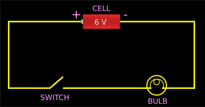
A 6 V bulb, a 6 V cell and a switch
2. Measure the resistance of the bulb when the switch is turned off.
• A multimeter can be used for measuring the resistance even when the switch is turned off
3. Remove the multimeter. Turn on the switch. Let the bulb glow for some time.
4. Turn off the switch. Immediately measure the resistance again.
• We can see that, this second reading is higher
■ What is the reason for this higher reading?
Ans: When the bulb glowed for some time, it's temperature increased.
• So in the second reading, we were measuring the resistance of a 'hot resistor'.
• So we can write: When temperature increases, resistance increases
From the above two activities, we come to know about four 'factors which affect the resistance'.
Factor 1. Resistance depends on the nature of the material
Factor 2. Resistance depends on the thickness
• Thickness is same as 'area of cross section'
• We saw this:
When area of cross section (A) increases, resistance (R) decreases
• So when one quantity increases, the other quantity decreases
• This is an inverse relation. It can be represented mathematically as: R ∝ 1⁄A
• That is., R is proportional to 1⁄A
Factor 3. Resistance depends on the length
• We saw this:
When length (l) decreases , resistance (R) decreases
• So when one quantity decreases, the other quantity also decreases
• This is a direct relation. It can be represented mathematically as: R ∝ l
• That is., R is proportional to l.
Factor 4. Resistance depends on the temperature
• We saw this:
When temperature increases, resistance also increases
• So when one quantity increases, the other quantity also increases
• This is a direct relation. We do not need to represent this mathematically at present. We will see it in higher classes when we do advanced problems.
But for our present problems, we need to combine the mathematical representations in (2) and (3):
• Note that 'l' is in the numerator and 'A' is in the denominator.
• So, when we combine them, we get: R ∝ l ⁄A
• We can avoid the '∝' symbol by introducing a 'constant of proportionality'. See details here.
That is., R = (a constant) × l ⁄A
• This constant is given a special name: 'Resistivity of the material which is used to make that conductor'
♦ Or simply 'Resistivity'
• It's symbol is 'ρ'. It is the Greek letter 'rho'
• So we can write: R = ρ × l ⁄A
• Rearranging this, we get: ρ = (RA)⁄l
Now consider a simple problem:
■ The resistance of a resistor is R Ω. It's length is 1 m. It's area of cross section is 1 m2. Calculate the resistivity of the material used for making that resistor
Solution:
• We have: ρ = (RA)⁄l
• Substituting the known values, we get: ρ = (R×1)⁄1 = R×1 = R
From the above problem, we can formulate a definition for resistivity. We will write it in steps:
1. Consider a piece of any material.
• Let it be made up of any material like iron, copper, nichrome etc.,
• Let it's length be 1 m
• Let it's cross sectional area be 1 m2
2. We want to know the resistance which this resistor is able to apply (to a current that flows through it)
• For that, we can use the relation that we derived previously: R = ρ × l ⁄A
• Substituting the known values, we get: R = ρ × 1⁄1 = (ρ × 1) = ρ
• So we get R = ρ.
3. We started off with a piece of material whose length is 1 m and area of cross section is 1 m2.
• We obtained the result:
Resistance of that piece = resistivity of the material with which that piece is made
• This result helps us to give a definition for resistivity. The official definition is:
■ Resistivity of a substance is the resistance of the conductor of unit length and unit area of cross section.
• The resistivity of a substance is a constant at fixed temperature.
• Resistivity will be different for different materials
Now we will try to establish a unit for resistivity. The steps are shown below:

Types of resistors:
• We use different types of resistors in electric circuits. Some images can be seen here.
• If we want to purchase a particular resistor, we must know it's 'resistance in ohms'
♦ So the 'resistance in ohms' must be marked on every resistor.
• It is convenient to 'use colour code' rather than to 'write the exact numerical value' on the resistor
■ Let us see how colour coding works. We will use an example:
Consider fig.8.21 below. It is taken from wikimedia commons:
Source 1.
Source 2.
1. There are 4 colour bands. First we will consider the first three bands
2. The first band is red.
♦ It indicates the digit '2'. This is taken from the chart shown on right side
• The second band is violet
♦ It indicates the digit '7'
So in this step we get '27'
3. The third band indicates the number with which '27' is to be multiplied
• Our third band is green. So we have to multiply by 100K
• 'K' indicates 1000. So 100K is 100 × 1000 = 100000
4. So we have to multiply '27' by 100000. We get: 2700000
• This is the value of the resistance. We can write:
• The resistance of the given resistor is 2700000 Ω.
• This can be shortened as: 2700 kΩ.
5. Now we come to the fourth band. It is silver in colour.
• So the tolerance is ±10%
• The '±' sign indicates 'above or below'. It can be explained as follows:
♦ 10% of 2700 = (2700 × 10⁄100) = (2700 × 0.1) = 270
♦ 2700 + 270 = 2970
♦ 2700 - 270 = 2430
• So the actual resistance can be any value from 2430 kΩ to 2970 kΩ.
• If the fourth band is absent, tolerance should be taken as ±20%
Variable resistance
1. In the above discussion, we derived the relation: R ∝ l
• That is., Resistance is proportional to l.
• If we increase the length of a conductor, the resistance that it applies (against the flow of current through it) will increase
• If we decrease the length of a conductor, the resistance that it applies (against the flow of current through it) will decrease
Let us do an activity. The steps are written below:
1. Make a circuit with the following components:
An ammeter, switch, cells and a bulb.
2. One end of the circuit must be free and flexible
This free end should have a pointer J which should be able to touch the ends of the following conductors:
(i) An iron conductor PA
(ii) An aluminium conductor PB (having same length as PA)
(iii) A nichrome conductor PC (having same length as PA and PB)
(iv) A nichrome conductor PD (having same length as PA, PB and PC, but twice the thickness)
(v) A nichrome conductor PE (having same thickness as PA, PB and PC, but twice the length)
• The circuit diagram is shown in fig.8.19 below:
 |
| Fig.8.19 |
Complete the circuit by touching the pointer at A
• Note down the ammeter reading
• Note down the intensity of light from the bulb
• Turn off the switch. This completes one trial.
4. Turn on the switch
Complete the circuit by touching the pointer at B
• Note down the ammeter reading
• Note down the intensity of light from the bulb
• Turn off the switch. This completes the second trial.
5. Turn on the switch
Complete the circuit by touching the pointer at C
• Note down the ammeter reading
• Note down the intensity of light from the bulb
• Turn off the switch. This completes the third trial.
- - -
- - -
Continue for the remaining points E and D
The trials are complete. The observations are tabulated below:
 |
| Table.8.3 |
point 1:
1. Consider the first 3 trials:
• We have, same voltage, same length and same thickness
• But currents are different. What is the reason?
Ans: We have: I = V⁄R
• V is the same. So if there is a change in I, it has to be due to the change in R
• That is., the resistance offered by PA, PB and PC are different
2. All three have same length and same thickness. Only difference is in 'material'. So we can write:
■ Iron , aluminium and nichrome will offer different resistances because they are different materials
• Aluminium offers the least resistance among the three. So highest current is in trial 2
Point 2:
1. Consider the trials 3 and 4:
• We have, same voltage, same length and same material
• But currents are different. What is the reason?
Ans: We have: I = V⁄R .
• V is the same. So if there is a change in I, it has to be due to the change in R
• That is., the resistance offered by PC, and PD are different
2. Both have same length and same material. Only difference is in 'thickness'. So we can write:
■ Even if length and materials are the same, two resistors having different thicknesses will offer different resistances
• In our present case, PD has greater thickness. It has greater current. So we can write:
■ When the thickness increases, resistance decreases
A similar situation is shown in fig.8.20 below:
 |
| Fig.8.20 |
♦ In fig.8.20(a), the tunnel is narrow. People will find it difficult to pass freely
♦ In fig.8.20(b), the tunnel is broad. People will find it easy to pass freely
• Current will also find it easy to pass through a thick wire
Point 3:
1. Consider the trials 3 and 5:
• We have, same voltage, same thickness and same material
• But currents are different. What is the reason?
Ans: We have: I = V⁄R
• V is the same. So if there is a change in I, it has to be due to the change in R
• That is., the resistance offered by PC, and PE are different
2. Both have same thickness and same material. Only difference is in 'length'. So we can write:
■ Even if thickness and materials are the same, two resistors with different lengths will offer different resistances
• In our present case, PE has greater length. It has lesser current. So we can write:
■ When the length increases, resistance increases
We can confirm this by doing an extra trial:
(i) In the trial 5, we touched the end of PE. Do it again. Note the intensity of light.
(ii) Slowly slide the pointer from E to P
• We can see that, the intensity of the light increases as the pointer moves from E to P
(iii) The reason is that, the length through which current has to travel through nichrome goes on decreasing.
• So resistance goes on decreasing.
• Thus current goes on increasing.
• Thus the intensity goes on increasing
Another activity:
This activity is performed to find the relation between temperature and resistance. We will write the steps:
1. Make a simple circuit with the following components:
A 6 V bulb, a 6 V cell and a switch
• A multimeter can be used for measuring the resistance even when the switch is turned off
3. Remove the multimeter. Turn on the switch. Let the bulb glow for some time.
4. Turn off the switch. Immediately measure the resistance again.
• We can see that, this second reading is higher
■ What is the reason for this higher reading?
Ans: When the bulb glowed for some time, it's temperature increased.
• So in the second reading, we were measuring the resistance of a 'hot resistor'.
• So we can write: When temperature increases, resistance increases
From the above two activities, we come to know about four 'factors which affect the resistance'.
Factor 1. Resistance depends on the nature of the material
Factor 2. Resistance depends on the thickness
• Thickness is same as 'area of cross section'
• We saw this:
When area of cross section (A) increases, resistance (R) decreases
• So when one quantity increases, the other quantity decreases
• This is an inverse relation. It can be represented mathematically as: R ∝ 1⁄A
• That is., R is proportional to 1⁄A
Factor 3. Resistance depends on the length
• We saw this:
When length (l) decreases , resistance (R) decreases
• So when one quantity decreases, the other quantity also decreases
• This is a direct relation. It can be represented mathematically as: R ∝ l
• That is., R is proportional to l.
Factor 4. Resistance depends on the temperature
• We saw this:
When temperature increases, resistance also increases
• So when one quantity increases, the other quantity also increases
• This is a direct relation. We do not need to represent this mathematically at present. We will see it in higher classes when we do advanced problems.
But for our present problems, we need to combine the mathematical representations in (2) and (3):
• Note that 'l' is in the numerator and 'A' is in the denominator.
• So, when we combine them, we get: R ∝ l ⁄A
• We can avoid the '∝' symbol by introducing a 'constant of proportionality'. See details here.
That is., R = (a constant) × l ⁄A
• This constant is given a special name: 'Resistivity of the material which is used to make that conductor'
♦ Or simply 'Resistivity'
• It's symbol is 'ρ'. It is the Greek letter 'rho'
• So we can write: R = ρ × l ⁄A
• Rearranging this, we get: ρ = (RA)⁄l
Now consider a simple problem:
■ The resistance of a resistor is R Ω. It's length is 1 m. It's area of cross section is 1 m2. Calculate the resistivity of the material used for making that resistor
Solution:
• We have: ρ = (RA)⁄l
• Substituting the known values, we get: ρ = (R×1)⁄1 = R×1 = R
From the above problem, we can formulate a definition for resistivity. We will write it in steps:
1. Consider a piece of any material.
• Let it be made up of any material like iron, copper, nichrome etc.,
• Let it's length be 1 m
• Let it's cross sectional area be 1 m2
2. We want to know the resistance which this resistor is able to apply (to a current that flows through it)
• For that, we can use the relation that we derived previously: R = ρ × l ⁄A
• Substituting the known values, we get: R = ρ × 1⁄1 = (ρ × 1) = ρ
• So we get R = ρ.
3. We started off with a piece of material whose length is 1 m and area of cross section is 1 m2.
• We obtained the result:
Resistance of that piece = resistivity of the material with which that piece is made
• This result helps us to give a definition for resistivity. The official definition is:
■ Resistivity of a substance is the resistance of the conductor of unit length and unit area of cross section.
• The resistivity of a substance is a constant at fixed temperature.
• Resistivity will be different for different materials
Now we will try to establish a unit for resistivity. The steps are shown below:

Types of resistors:
• We use different types of resistors in electric circuits. Some images can be seen here.
• If we want to purchase a particular resistor, we must know it's 'resistance in ohms'
♦ So the 'resistance in ohms' must be marked on every resistor.
• It is convenient to 'use colour code' rather than to 'write the exact numerical value' on the resistor
■ Let us see how colour coding works. We will use an example:
Consider fig.8.21 below. It is taken from wikimedia commons:
Source 1.
Source 2.
 |
| Fig.8.21 |
2. The first band is red.
♦ It indicates the digit '2'. This is taken from the chart shown on right side
• The second band is violet
♦ It indicates the digit '7'
So in this step we get '27'
3. The third band indicates the number with which '27' is to be multiplied
• Our third band is green. So we have to multiply by 100K
• 'K' indicates 1000. So 100K is 100 × 1000 = 100000
4. So we have to multiply '27' by 100000. We get: 2700000
• This is the value of the resistance. We can write:
• The resistance of the given resistor is 2700000 Ω.
• This can be shortened as: 2700 kΩ.
5. Now we come to the fourth band. It is silver in colour.
• So the tolerance is ±10%
• The '±' sign indicates 'above or below'. It can be explained as follows:
♦ 10% of 2700 = (2700 × 10⁄100) = (2700 × 0.1) = 270
♦ 2700 + 270 = 2970
♦ 2700 - 270 = 2430
• So the actual resistance can be any value from 2430 kΩ to 2970 kΩ.
• If the fourth band is absent, tolerance should be taken as ±20%
Variable resistance
1. In the above discussion, we derived the relation: R ∝ l
• That is., Resistance is proportional to l.
• If we increase the length of a conductor, the resistance that it applies (against the flow of current through it) will increase
• If we decrease the length of a conductor, the resistance that it applies (against the flow of current through it) will decrease
2. So if we can make a 'resistor device' in which, the length can be increased or decreased, we will get different 'resistance values' from a single resistor
■ Rheostat is a device designed on the basis of this principle
• A rheostat can be seen here. It is obtained from wikimedia commons.
• The conductor is wound over an insulator. A sliding contact moves on the horizontal bar at the top.
• As the slider is moved towards left or right, the contact point with the conductor changes
• So the 'length of the conductor coming inside the circuit' changes.
• Thus the desired resistance can be obtained
• If we can change the resistance value, we can change the current.
■ Rheostat is a device used to regulate the current in a circuit by changing the resistance
• The symbol of a variable resistor is:

• A rheostat can be seen here. It is obtained from wikimedia commons.
• As the slider is moved towards left or right, the contact point with the conductor changes
• So the 'length of the conductor coming inside the circuit' changes.
• Thus the desired resistance can be obtained
• If we can change the resistance value, we can change the current.
■ Rheostat is a device used to regulate the current in a circuit by changing the resistance
• The symbol of a variable resistor is: