In the section 8.4, we saw series connection of resistors. In the previous section 8.5 we saw parallel connection of resistors. In this section, we will see a comparison between the two. We will write the comparison in steps:
1. Consider fig.8.25(a) below:
• People are crossing 3 canals. For that purpose, 3 bridges are provided.
2. Because of the necessity to use the bridges, the movement of the people is somewhat constrained.
• We can compare this arrangement to resistors in series. When resistors are provided, free flow of current is constrained.
3. If any one of the bridges in series is broken down, the movement of people will no longer be possible. This is shown in fig.b.
• If in our home wiring, a TV, refrigerator and electric fan are connected in series, we will have to turn all the three of them on.
• If any one is turned off, the circuit will not complete and so the other devices will also be turned off
4. Now consider fig.8.26(a) below:
• People are crossing a canal. 3 bridges are provided for the purpose.
• People can use any one of the three bridges.
• So there is greater freedom of movement.
5. This arrangement can be compared to resistors in parallel.
• Even if one of the bridges is broken down, people can take the other bridges.
• The devices in our home are connected in parallel circuits.
• So even if one or two devices are turned off, the other devices will work.
Let us do an activity to compare series and parallel resistors:
• In this activity, we have to make two circuits. They are shown in figs.8.27 (a) and (b).
• We can note the peculiarities of each:
Circuit 1: There are two 6 W, 6 V bulbs, a 6 V battery and a switch
♦ The two bulbs are connected in parallel
Circuit 2: Components are the same: Two 6 W, 6 V bulbs, a 6 V battery and a switch
♦ The two bulbs are connected in series
• Now we can begin the trials:
Trial 1: Turn both switches on. This is shown in figs.8.27(a) and (b)
Observations:
(i) The two bulbs in circuit 1 glow with equal intensity. Let this intensity be C1T1
['C1' for circuit 1 and 'T1' for trial 1]
(ii) The two bulbs in circuit 2 glow with equal intensity. Let this intensity be C2T1
(iii) The intensity in circuit 1 is more. That is., C1T1 > C2T1
• Before proceeding to trial 2, we will analyse the above observations. We will write the analysis in steps:
1. We see that, bulbs connected in series are dim.
• We want to know the reason.
2. All bulbs are of the same type. So they have the same resistance. Let this be 'r'
• Let us calculate the effective resistance 'R' in circuit 1:
• The resistors are connected in parallel.
• We have: 1⁄R = (1⁄r + 1⁄r) = 2⁄r ⟹ R = r⁄2
• So total current I = V⁄R = 2V⁄r
3. At the junction, this current will branch into two: I1 and I2
We have:
• I1 = V1⁄r
• I2 = V2⁄r
4. But in parallel connection, V1 = V2 = V
• So we get: I1 = I2 = V⁄r = 6⁄r
• Both the currents are the same. So the two bulbs glow with equal intensity C1T1
5. Let us calculate the effective resistance in circuit 2:
• The resistors are connected in series
• We have: R = (r+r) = 2r
6. Total current in the circuit = V⁄2r
• This current will flow through the two bulbs.
• So current in each of the two bulbs in series = V⁄2r = 6⁄2r = 3⁄r
• Since both bulbs have the same current, they both glow with the same intensity C2T1
7. Now let us compare the two systems:
• Current for each bulb in the parallel connection = 6⁄r
• Current for each bulb in the series connection = 3⁄r
• Obviously, more current is passing through the bulbs in parallel connection.
■ So they glow with greater intensity. That is: C1T1 > C2T1.
Trial 2: Remove one bulb from each circuit. This is shown in figs.8.28 (a) and (b) below:
• Note that, when a bulb is removed from circuit 2, alternate path has to be given. Other wise the circuit will not become complete
• But no such alternate path is required for circuit 1
• Turn both the switches on
Observations:
(i) Let the intensity of light in circuit 1 be C1T2.
• We see that this intensity is same as what was seen in trial 1. That is., C1T2 = C1T1
(ii) Let the intensity of light in circuit 2 be C2T2.
• We see that this intensity is more than what was seen in trial 1. That is., C2T2 > C2T1
• Also we see that this intensity in circuit 2 is same as that in circuit 1 in trial 1
That is., C2T2 = C1T2 = C1T1
1. Let us calculate the effective resistance in circuit 1:
• There is only one bulb. So the effective resistance is r
• Current I = V⁄r = 6⁄r
• Note that, this is the same current that each of the bulbs in circuit 1 had, in trial 1.
• So the intensity is same.
2. Let us calculate the effective resistance in circuit 2:
• There is only one bulb. So the effective resistance is r
• Current I = V⁄r = 6⁄r
• Note that, this is the same current that each of the bulbs in circuit 1 had, in trial 1.
• So the intensity is same.
A virtual lab to make different circuits can be seen here.
Now we will see some solved examples based on what we have learned so far in this chapter:
Solved example 8.1
A resistor has a length of 1m. It's area of cross section is 1 m2. It's resistance value is R Ω.
Then answer the following questions:
(i) If the area is kept at 1 m2 and the length is doubled, what will be the resistance?
(ii) If the length is kept at 1 m and area is doubled, what will be the resistance?
(iii) If both length and area are doubled, what will be the resistance?
(iv) If the length is kept at 1 m and area is halved, what will be the resistance?
Solution:
• We have: R = ρ × l ⁄A
• Given l = 1 m, A = 1 m2.
• Substituting in the formula for R, we get: R = ρ × 1 ⁄1 = ρ Ω.
■ So the resistance value 'R' of the original resistor is equal to ρ. That is., R = ρ.
Part (i):
• Given l = 2 m, A = 1 m2.
• Let the new resistance value be R1
• We get: R1 = ρ × 2 ⁄1 = (2ρ) Ω = (2R) Ω. [∵ ρ = R]
• So we can write: The new resistance is twice the original value
Part (ii):
• Given l = 1 m, A = 2 m2.
• Let the new resistance value be R2
• We get: R2 = ρ × 1 ⁄2 = (0.5ρ) Ω = (0.5R) Ω. [∵ ρ = R]
• So we can write: The new resistance is half the original value
Part (iii):
• Given l = 2 m, A = 1 m2.
• Let the new resistance value be R3
• We get: R3 = ρ × 2 ⁄2 = (ρ) Ω = (R) Ω. [∵ ρ = R]
• So we can write: The new resistance same as the original value
Part (iv):
• Given l = 1 m, A = 0.5 m2.
• Let the new resistance value be R4
• We get: R4 = ρ × 1 ⁄0.5 = (2ρ) Ω = (2R) Ω. [∵ ρ = R]
• So we can write: The new resistance is twice the original value
Solved example 8.2
What is the current if 4 Ω and 2 Ω resistors are connected in series and 6 V potential difference is applied?
Solution:
1. When resistors are connected in series, the effective resistance R is given by:
R = (R1+ R2 + . . . + Rn)
• So in our present case, R = (4+2) = 6 Ω.
2. We have: I = V⁄R
• Substituting the values, we get: I = 6⁄6 = 1 A
Solved example 8.3
What is the current if 12 Ω and 4 Ω resistors are connected in parallel and 12 V potential difference is applied?
Solution:
1. When resistors are connected in parallel, the effective resistance R is given by:
R = (1⁄R1 + 1⁄R2+ 1⁄R3 + . . . + 1⁄Rn)
• So in our present case, 1⁄R = (1⁄12 + 1⁄4) = 4⁄12 = 1⁄3
⟹ R = 3 Ω
2. We have: I = V⁄R
• Substituting the values, we get: I = 12⁄3 = 4 A
Solved example 8.4
(a) 10 resistors of 2 Ω each are connected in parallel. Calculate the effective resistance.
(b) 10 resistors of 2 Ω each are connected in series. Calculate the effective resistance.
Solution:
Part (a):
• When resistors having the same resistance value are connected in parallel, the effective resistance is given by: R = r⁄n
• Where R is the effective resistance and r is the resistance of individual resistors
• So we get: R = 2⁄10 = 1⁄5 Ω.
Part (b):
• When resistors having the same resistance value are connected in series, the effective resistance is given by: R = nr
• Where R is the effective resistance and r is the resistance of individual resistors
• So we get: R = 20 × 2 = 20 Ω.
Solved example 8.5
The resistance of a 10 cm long wire is 12 Ω. If this is folded into two parts of equal length and included in a circuit, how much will be the resistance produced?
Solution:
1. We have: R = ρ × l ⁄A
• Given R = 12 Ω, l = 10 cm = 0.1 m
2. Substituting in the formula for R, we get: 12 = ρ × 0.1 ⁄A
⟹ 12 ⁄0.1 = ρ × 1 ⁄A
⟹ ρ × 1 ⁄A = 120
3. Now the wire is folded into two equal parts. So we get:
• New length l1 = 5 cm = 0.05 m
• New area A1 = 2A
• Let the new resistance be R1
4. Substituting in the formula for R, we get: R1 = ρ × 0.05 ⁄2A .
⟹ R1 ⁄0.05 = ρ × 1 ⁄2A ⟹ 2R1 ⁄0.05 = ρ × 1 ⁄A
⟹ 40R1 = ρ × 1 ⁄A.
5. But from (2), we have: ρ × 1 ⁄A = 120
So (4) becomes:
40R1 = 120 ⟹ R1 = 3 Ω.
Solved example 8.6
(a) A potential difference of 6 V is applied across a conductor having 12 Ω resistance. How much current will pass through it?
(b) How many times will the current increase if the length of the resistor is halved and potential difference is doubled?
Solution:
Part (a):
1. The given values are: V = 6 V, R = 12 Ω
We have to calculate I
2. We have: I = V⁄R
Substituting the known values, we get: I = 6⁄12 = 0.5 A
Part (b):
1. The length of the resistor is halved. We have to find the new resistance.
• Let l be the original length and A the original area of cross section
• Then original resistance R = 12 = ρ × l ⁄A ⟹ ρ = 12 × (A ⁄l)
2. Let l1 be the new length. Given that l1 = 0.5l
• Area of cross section does not change. So it is A
• So new resistance R1 = ρ × l1 ⁄A = ρ × 0.5l ⁄A
⟹ R1 = 0.5 × ρ × (l ⁄A)
3. From (1), we have: ρ = 12 × (A ⁄l)
• Substituting this in 2, we get:
R1 = 0.5 × [12 × (A ⁄l)] × (l ⁄A) = 0.5 × 12 = 6 Ω.
4. The voltage is doubled. So the new voltage is 12 V
So new current = I1 = V⁄R= 12⁄6 = 2 A
5. We have: I1⁄I = 2⁄0.5 = 4
• So the current increases 4 times.
Solved example 8.7
What mode of connection of three resistors of 3 Ω each will produce minimum resistance? What will produce maximum resistance? Draw the diagram and calculate the effective resistance
Solution:
• The two modes possible are: Series and parallel. They are shown in figs.8.29 (a) and (b) respectively
• The effective resistance in series connection is given by R = nr (Details here)
♦ So for our present problem, R = 3 × 3 = 9 Ω
• The effective resistance in series connection is given by R = r⁄n (Details here)
♦ So for our present problem, R = 3⁄3 = 1 Ω.
• So we can write:
♦ Series mode creates maximum resistance
♦ Parallel mode creates minimum resistance
Solved example 8.8
Draw a circuit having a battery, 3 bulbs, a switch and rheostat. In how many ways can the bulbs be connected? When is more light obtained?
Solution:
• The four different possibilities are shown in fig.8.30 below:
♦ In all the cases, the voltage available from the battery is the same. Let it be V
♦ In all the cases, the resistance of each bulb is the same. Let it be r
Fig.8.30(a):
1. Effective resistance = nr = 3r
2. So current released from the battery = I = V⁄R = V⁄3r
• Each of the 3 bulbs gets this current
Fig.8.30(b):
1. Effective resistance = r⁄n = r⁄3
2. So current released from the battery = I = V⁄R = 3V⁄r
3. At the junction, this current will split into 3 equal parts because, resistance of all bulbs are the same.
4. So each of the 3 bulbs gets V⁄r
Fig.8.30(c):
1. Effective resistance = (nr + r⁄n) = (r + r⁄2 ) = 3r⁄2
2. So current released from the battery = I = V⁄R = 2V⁄3r
• The first bulb gets this current.
3. The two bulbs in parallel will get half of this current, which is equal to V⁄3r.
Fig.8.30(d):
1. Inside the parallel mode, two bulbs are in series. Their effective resistance = 2r
2. So the effective resistance is given by: 1⁄R = (1⁄R1 + 1⁄R2)
⟹ 1⁄R = (1⁄2r + 1⁄r) = 3⁄2r.
• Effective resistance = R = 2r⁄3
3. So current released from the battery = I = V⁄R = 3V⁄2r
4. Current in the upper branch = V⁄resistance of upper branch = V⁄2r
5. Current in the lower branch = V⁄resistance of lower branch = V⁄r
■ Conclusion:
• The currents in different bulbs are:
V⁄3r , V⁄r , 2V⁄3r , V⁄3r , V⁄2r ,V⁄r
• The highest value is V⁄r . The two cases below has this current. They glow with maximum light
♦ All bulbs in fig.(b)
♦ The bottom bulb in fig.(d)
• The lowest value is V⁄3r . The two cases below has this current. They glow with least light
♦ All bulbs in fig.(a)
♦ The two parallel bulbs in fig.(d)
Solved example 8.9
In a circuit, 3 cells are connected as shown in fig.8.31 below. What is the resultant voltage?
Solution:
• The two cells in parallel will give an effective voltage of 1.5 V
• So the net effective voltage is (1.5 + 1.5) = 3 V
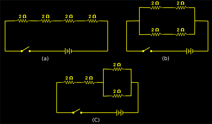
Solved example 8.10
Find the effective resistance in the three circuits shown in fig.8.32 below:
Solution:
Fig.8.32(a):
• Effective resistance = nr = 4 × 2 = 8 Ω.
Fig.8.32(b):
• Effective resistance in upper branch = nr = 2 × 2 = 4 Ω
• Effective resistance in lower branch = nr = 2 × 2 = 4 Ω
• Net effect = r⁄n = 4⁄2 = 2 Ω
Fig.8.32(c):
• Net effect of the parallel resistors = r⁄n = 2⁄2 = 1 Ω.
• Net effect of the whole circuit = (2+2+1) = 5 Ω
1. Consider fig.8.25(a) below:
 |
| Fig.8.25 |
2. Because of the necessity to use the bridges, the movement of the people is somewhat constrained.
• We can compare this arrangement to resistors in series. When resistors are provided, free flow of current is constrained.
3. If any one of the bridges in series is broken down, the movement of people will no longer be possible. This is shown in fig.b.
• If in our home wiring, a TV, refrigerator and electric fan are connected in series, we will have to turn all the three of them on.
• If any one is turned off, the circuit will not complete and so the other devices will also be turned off
4. Now consider fig.8.26(a) below:
 |
| Fig.8.26 |
• People can use any one of the three bridges.
• So there is greater freedom of movement.
5. This arrangement can be compared to resistors in parallel.
• Even if one of the bridges is broken down, people can take the other bridges.
• The devices in our home are connected in parallel circuits.
• So even if one or two devices are turned off, the other devices will work.
Let us do an activity to compare series and parallel resistors:
• In this activity, we have to make two circuits. They are shown in figs.8.27 (a) and (b).
• We can note the peculiarities of each:
Circuit 1: There are two 6 W, 6 V bulbs, a 6 V battery and a switch
♦ The two bulbs are connected in parallel
Circuit 2: Components are the same: Two 6 W, 6 V bulbs, a 6 V battery and a switch
♦ The two bulbs are connected in series
• Now we can begin the trials:
Trial 1: Turn both switches on. This is shown in figs.8.27(a) and (b)
 |
| Fig.8.27 |
(i) The two bulbs in circuit 1 glow with equal intensity. Let this intensity be C1T1
['C1' for circuit 1 and 'T1' for trial 1]
(ii) The two bulbs in circuit 2 glow with equal intensity. Let this intensity be C2T1
(iii) The intensity in circuit 1 is more. That is., C1T1 > C2T1
• Before proceeding to trial 2, we will analyse the above observations. We will write the analysis in steps:
1. We see that, bulbs connected in series are dim.
• We want to know the reason.
2. All bulbs are of the same type. So they have the same resistance. Let this be 'r'
• Let us calculate the effective resistance 'R' in circuit 1:
• The resistors are connected in parallel.
• We have: 1⁄R = (1⁄r + 1⁄r) = 2⁄r ⟹ R = r⁄2
• So total current I = V⁄R = 2V⁄r
3. At the junction, this current will branch into two: I1 and I2
We have:
• I1 = V1⁄r
• I2 = V2⁄r
4. But in parallel connection, V1 = V2 = V
• So we get: I1 = I2 = V⁄r = 6⁄r
• Both the currents are the same. So the two bulbs glow with equal intensity C1T1
5. Let us calculate the effective resistance in circuit 2:
• The resistors are connected in series
• We have: R = (r+r) = 2r
6. Total current in the circuit = V⁄2r
• This current will flow through the two bulbs.
• So current in each of the two bulbs in series = V⁄2r = 6⁄2r = 3⁄r
• Since both bulbs have the same current, they both glow with the same intensity C2T1
7. Now let us compare the two systems:
• Current for each bulb in the parallel connection = 6⁄r
• Current for each bulb in the series connection = 3⁄r
• Obviously, more current is passing through the bulbs in parallel connection.
■ So they glow with greater intensity. That is: C1T1 > C2T1.
Trial 2: Remove one bulb from each circuit. This is shown in figs.8.28 (a) and (b) below:
 |
| Fig.8.28 |
• But no such alternate path is required for circuit 1
• Turn both the switches on
Observations:
(i) Let the intensity of light in circuit 1 be C1T2.
• We see that this intensity is same as what was seen in trial 1. That is., C1T2 = C1T1
(ii) Let the intensity of light in circuit 2 be C2T2.
• We see that this intensity is more than what was seen in trial 1. That is., C2T2 > C2T1
• Also we see that this intensity in circuit 2 is same as that in circuit 1 in trial 1
That is., C2T2 = C1T2 = C1T1
1. Let us calculate the effective resistance in circuit 1:
• There is only one bulb. So the effective resistance is r
• Current I = V⁄r = 6⁄r
• Note that, this is the same current that each of the bulbs in circuit 1 had, in trial 1.
• So the intensity is same.
2. Let us calculate the effective resistance in circuit 2:
• There is only one bulb. So the effective resistance is r
• Current I = V⁄r = 6⁄r
• Note that, this is the same current that each of the bulbs in circuit 1 had, in trial 1.
• So the intensity is same.
A virtual lab to make different circuits can be seen here.
Now we will see some solved examples based on what we have learned so far in this chapter:
Solved example 8.1
A resistor has a length of 1m. It's area of cross section is 1 m2. It's resistance value is R Ω.
Then answer the following questions:
(i) If the area is kept at 1 m2 and the length is doubled, what will be the resistance?
(ii) If the length is kept at 1 m and area is doubled, what will be the resistance?
(iii) If both length and area are doubled, what will be the resistance?
(iv) If the length is kept at 1 m and area is halved, what will be the resistance?
Solution:
• We have: R = ρ × l ⁄A
• Given l = 1 m, A = 1 m2.
• Substituting in the formula for R, we get: R = ρ × 1 ⁄1 = ρ Ω.
■ So the resistance value 'R' of the original resistor is equal to ρ. That is., R = ρ.
Part (i):
• Given l = 2 m, A = 1 m2.
• Let the new resistance value be R1
• We get: R1 = ρ × 2 ⁄1 = (2ρ) Ω = (2R) Ω. [∵ ρ = R]
• So we can write: The new resistance is twice the original value
Part (ii):
• Given l = 1 m, A = 2 m2.
• Let the new resistance value be R2
• We get: R2 = ρ × 1 ⁄2 = (0.5ρ) Ω = (0.5R) Ω. [∵ ρ = R]
• So we can write: The new resistance is half the original value
Part (iii):
• Given l = 2 m, A = 1 m2.
• Let the new resistance value be R3
• We get: R3 = ρ × 2 ⁄2 = (ρ) Ω = (R) Ω. [∵ ρ = R]
• So we can write: The new resistance same as the original value
Part (iv):
• Given l = 1 m, A = 0.5 m2.
• Let the new resistance value be R4
• We get: R4 = ρ × 1 ⁄0.5 = (2ρ) Ω = (2R) Ω. [∵ ρ = R]
• So we can write: The new resistance is twice the original value
Solved example 8.2
What is the current if 4 Ω and 2 Ω resistors are connected in series and 6 V potential difference is applied?
Solution:
1. When resistors are connected in series, the effective resistance R is given by:
R = (R1+ R2 + . . . + Rn)
• So in our present case, R = (4+2) = 6 Ω.
2. We have: I = V⁄R
• Substituting the values, we get: I = 6⁄6 = 1 A
Solved example 8.3
What is the current if 12 Ω and 4 Ω resistors are connected in parallel and 12 V potential difference is applied?
Solution:
1. When resistors are connected in parallel, the effective resistance R is given by:
R = (1⁄R1 + 1⁄R2+ 1⁄R3 + . . . + 1⁄Rn)
• So in our present case, 1⁄R = (1⁄12 + 1⁄4) = 4⁄12 = 1⁄3
⟹ R = 3 Ω
2. We have: I = V⁄R
• Substituting the values, we get: I = 12⁄3 = 4 A
Solved example 8.4
(a) 10 resistors of 2 Ω each are connected in parallel. Calculate the effective resistance.
(b) 10 resistors of 2 Ω each are connected in series. Calculate the effective resistance.
Solution:
Part (a):
• When resistors having the same resistance value are connected in parallel, the effective resistance is given by: R = r⁄n
• Where R is the effective resistance and r is the resistance of individual resistors
• So we get: R = 2⁄10 = 1⁄5 Ω.
Part (b):
• When resistors having the same resistance value are connected in series, the effective resistance is given by: R = nr
• Where R is the effective resistance and r is the resistance of individual resistors
• So we get: R = 20 × 2 = 20 Ω.
Solved example 8.5
The resistance of a 10 cm long wire is 12 Ω. If this is folded into two parts of equal length and included in a circuit, how much will be the resistance produced?
Solution:
1. We have: R = ρ × l ⁄A
• Given R = 12 Ω, l = 10 cm = 0.1 m
2. Substituting in the formula for R, we get: 12 = ρ × 0.1 ⁄A
⟹ 12 ⁄0.1 = ρ × 1 ⁄A
⟹ ρ × 1 ⁄A = 120
3. Now the wire is folded into two equal parts. So we get:
• New length l1 = 5 cm = 0.05 m
• New area A1 = 2A
• Let the new resistance be R1
4. Substituting in the formula for R, we get: R1 = ρ × 0.05 ⁄2A .
⟹ R1 ⁄0.05 = ρ × 1 ⁄2A ⟹ 2R1 ⁄0.05 = ρ × 1 ⁄A
⟹ 40R1 = ρ × 1 ⁄A.
5. But from (2), we have: ρ × 1 ⁄A = 120
So (4) becomes:
40R1 = 120 ⟹ R1 = 3 Ω.
Solved example 8.6
(a) A potential difference of 6 V is applied across a conductor having 12 Ω resistance. How much current will pass through it?
(b) How many times will the current increase if the length of the resistor is halved and potential difference is doubled?
Solution:
Part (a):
1. The given values are: V = 6 V, R = 12 Ω
We have to calculate I
2. We have: I = V⁄R
Substituting the known values, we get: I = 6⁄12 = 0.5 A
Part (b):
1. The length of the resistor is halved. We have to find the new resistance.
• Let l be the original length and A the original area of cross section
• Then original resistance R = 12 = ρ × l ⁄A ⟹ ρ = 12 × (A ⁄l)
2. Let l1 be the new length. Given that l1 = 0.5l
• Area of cross section does not change. So it is A
• So new resistance R1 = ρ × l1 ⁄A = ρ × 0.5l ⁄A
⟹ R1 = 0.5 × ρ × (l ⁄A)
3. From (1), we have: ρ = 12 × (A ⁄l)
• Substituting this in 2, we get:
R1 = 0.5 × [12 × (A ⁄l)] × (l ⁄A) = 0.5 × 12 = 6 Ω.
4. The voltage is doubled. So the new voltage is 12 V
So new current = I1 = V⁄R= 12⁄6 = 2 A
5. We have: I1⁄I = 2⁄0.5 = 4
• So the current increases 4 times.
Solved example 8.7
What mode of connection of three resistors of 3 Ω each will produce minimum resistance? What will produce maximum resistance? Draw the diagram and calculate the effective resistance
Solution:
• The two modes possible are: Series and parallel. They are shown in figs.8.29 (a) and (b) respectively
 |
| Fig.8.29 |
♦ So for our present problem, R = 3 × 3 = 9 Ω
• The effective resistance in series connection is given by R = r⁄n (Details here)
♦ So for our present problem, R = 3⁄3 = 1 Ω.
• So we can write:
♦ Series mode creates maximum resistance
♦ Parallel mode creates minimum resistance
Solved example 8.8
Draw a circuit having a battery, 3 bulbs, a switch and rheostat. In how many ways can the bulbs be connected? When is more light obtained?
Solution:
• The four different possibilities are shown in fig.8.30 below:
♦ In all the cases, the voltage available from the battery is the same. Let it be V
♦ In all the cases, the resistance of each bulb is the same. Let it be r
 |
| Fig.8.30 |
1. Effective resistance = nr = 3r
2. So current released from the battery = I = V⁄R = V⁄3r
• Each of the 3 bulbs gets this current
Fig.8.30(b):
1. Effective resistance = r⁄n = r⁄3
2. So current released from the battery = I = V⁄R = 3V⁄r
3. At the junction, this current will split into 3 equal parts because, resistance of all bulbs are the same.
4. So each of the 3 bulbs gets V⁄r
Fig.8.30(c):
1. Effective resistance = (nr + r⁄n) = (r + r⁄2 ) = 3r⁄2
2. So current released from the battery = I = V⁄R = 2V⁄3r
• The first bulb gets this current.
3. The two bulbs in parallel will get half of this current, which is equal to V⁄3r.
Fig.8.30(d):
1. Inside the parallel mode, two bulbs are in series. Their effective resistance = 2r
2. So the effective resistance is given by: 1⁄R = (1⁄R1 + 1⁄R2)
⟹ 1⁄R = (1⁄2r + 1⁄r) = 3⁄2r.
• Effective resistance = R = 2r⁄3
3. So current released from the battery = I = V⁄R = 3V⁄2r
4. Current in the upper branch = V⁄resistance of upper branch = V⁄2r
5. Current in the lower branch = V⁄resistance of lower branch = V⁄r
■ Conclusion:
• The currents in different bulbs are:
V⁄3r , V⁄r , 2V⁄3r , V⁄3r , V⁄2r ,V⁄r
• The highest value is V⁄r . The two cases below has this current. They glow with maximum light
♦ All bulbs in fig.(b)
♦ The bottom bulb in fig.(d)
• The lowest value is V⁄3r . The two cases below has this current. They glow with least light
♦ All bulbs in fig.(a)
♦ The two parallel bulbs in fig.(d)
Solved example 8.9
In a circuit, 3 cells are connected as shown in fig.8.31 below. What is the resultant voltage?
 |
| Fig.8.31 |
• The two cells in parallel will give an effective voltage of 1.5 V
• So the net effective voltage is (1.5 + 1.5) = 3 V
Solved example 8.10
Find the effective resistance in the three circuits shown in fig.8.32 below:
 |
| Fig.8.32 |
Fig.8.32(a):
• Effective resistance = nr = 4 × 2 = 8 Ω.
Fig.8.32(b):
• Effective resistance in upper branch = nr = 2 × 2 = 4 Ω
• Effective resistance in lower branch = nr = 2 × 2 = 4 Ω
• Net effect = r⁄n = 4⁄2 = 2 Ω
Fig.8.32(c):
• Net effect of the parallel resistors = r⁄n = 2⁄2 = 1 Ω.
• Net effect of the whole circuit = (2+2+1) = 5 Ω


